
Study of Over-Current Relay and Effect of PSM and TSM
Procedure
- Switch ON the power supply.
- Switch ON the MCB ON/OFF switch.
- Press the start button S1. Now start LED glows.
- Change the current value using current adjustment knob provided on the left side of the Relay setup module.
- After setting the fault current then press the stop button S2 and also press the reset button of the stop clock to make the displayed time to zero.
- Now press the start button S1. The stop clock starts counting and when relay trips, it stops counting. During the interval the disc in the relay will rotate.
- When the relay coil trips, the disc returns to the normal (original) position. Note down the relay current from the Relay-current meter and trip time from the stop clock.
- Repeat the above procedure from step 5 for various fault currents.
Observation
| S.No. | Plug Setting Multiplier | Fault Current Setting | Relay Fault Current | Measured Relay Tripping Time | Theoretical Relay Time |
|---|---|---|---|---|---|
| - | - | Amps | Amps | Sec. | Sec. |
| 1. | . | . | . | . | . |
| 2. | . | . | . | . | . |
| 3. | . | . | . | . | . |
| n. | . | . | . | . | . |
Connection Diagram
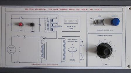
Fig 7.1 Connection Diagram of Over-Current Relay
Video for experiment:
Experiment 7. To Study the over-current relay and the effect of PSM and TSM.
Video-2
Video-2