


Speed Control of a DC Shunt Motor by Armature Resistance
DC MOTOR SIMULATION
CONNECTION DIAGRAM
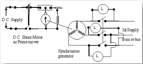
Fig 1.1:Connection diagram for synchronizing the alternator with 3-lamp method
This simulation shows how adding an external resistor ($R_{a_{ext}}$) in series with the armature affects the performance of a DC Shunt Motor. Adjust the load torque slider to see how the characteristics change under different load conditions.
Load Torque: 15.0 N·m
| Parameter | Symbol | Value |
|---|---|---|
| Terminal Voltage | $V_t$ | 240 V |
| Internal Armature Resistance | $R_{a_{int}}$ | 0.5 Ω |
| Field Resistance | $R_f$ | 120 Ω |
Underlying Principles
The behavior of the DC shunt motor is governed by the following equations:
- Field Current ($I_f$): The field winding is parallel to the supply, so its current is constant: $$I_f = \frac{V_t}{R_f}$$
- Armature Current ($I_a$): The motor develops an electromagnetic torque ($T_d$) to match the load torque ($T_L$). Since $T_d = K \cdot I_a$, the armature current is determined by the load: $$I_a = \frac{T_L}{K}$$ where $K$ is the motor constant.
- Back EMF ($E_b$) and Speed ($\omega$): Applying KVL to the armature circuit gives: $$V_t = E_b + I_a \cdot (R_{a_{int}} + R_{a_{ext}})$$ Since Back EMF is proportional to speed ($E_b = K \cdot \omega$), we can solve for speed: $$\omega = \frac{V_t - I_a \cdot (R_{a_{int}} + R_{a_{ext}})}{K}$$ This shows that for a constant load ($I_a$), angular speed ($\omega$) decreases as external resistance ($R_{a_{ext}}$) increases.